| Home |
Mechatronics |
About RMS |
DMC Sub |
Audio Design |
Education |
Kits & Parts |
Signal path
- Introduction
- Power supply
- Signal path
- Automatic current bias circuit
- Computer Modelling
- Measurements
Local feedback
The signal path in its purest form is shown below. There are three fully symmetric amplification stages.
The first stage is a gain stage with an ECC83 double triode in a "long-tailed pair" configuration where the common cathodes are spplied with a constant current from a BC550C transistor. This could have been made with a tube but that would require a high negative voltage and a transistor is better to get a high source impedance of the current source. The gain is approximately 70 (37dB). The coupling capacitor with the second stage is avoided by choosing a low collector voltage of 120V DC which is very well possible with an ECC83.
The second stage is the driver stage, optimised to give a large voltage swing. Also this stage consists of a double triode, the E88CC, connected in a symmetric "long-tailed pair" with a transistor current source. Its gain is approximately 28 (29 dB) and its low impedance of only a few kOhm makes it an ideal match for the input of the power tubes in view of the Miller capacitances.
The third stage is the power amplification stage consisting of the KT88 power tubes and the ring-core output transformer, designed by Menno van der Veen.
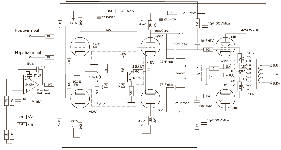
Several negative feedback loops can be distinguished, four local and one global
- The first feedback loop is over the gain and driver stage with a high quality polystyrene-foil 10 nF capacitor in series with a 1 MOhm resistor with a 10 pF Mica parallel capacitor. This feedback path reduces the total gain from 66dB to 40dB over the audio band and further reduces the non-linear distortion and the output impedance of the driver stage. The 10 nF capacitor is a 63V version for which reason it is connected after the coupling capacitor of 100 nF where the maximum voltage is acceptable. This has negligeable effects on the frequency behaviour as the impedance of the coupling capacitor is 0.1 times the impedance of the 10 nF capacitor. The 10 pF capacitor creates a high frequency fall off of the closed-loop gain at 16 kHz. I could have taken a 5 pF capacitor as there is enough phase margin (see computer modelling) but I could not find a ceramic capacitor of that value that was able to sustain voltages over 60 V so I took a very old mica capacitor that I had in stock from long ago.
- The second local feedback loop is from the output transformer to the cathodes of the power tube. This option is specially added to the transformer and creates a reduction of the output impedance of the power stage to 5 Ohm together with the "ultralinear" screen-grid connection.
- The third local feedback loop is the autobias circuit that keeps the bias current through the power tubes at a constant level.
- The fourth local feedback loop is the circuit around the LM108A Op-amp. This precision amplifier keeps the steady-state differential voltage level of the drives stage anodes equal to zero, thereby maximising the attainable voltage swing. After a 0.01* attenuator, to reduce the voltage to levels that can not harm the Op-Amp, the system integrates the differential voltage and feeds it back to the input.
- The global feedback loop is from the output to the input. This very limited overall feedback with an open-loop gain Gol of only 1.5 reduces the closed-loop gain in respect to the gain of the forward path with 1/(1+Gol)=2.5 equaling -8dB from 33dB to 25dB. This small open-loop gain also reduces the output impedance with the same factor 1/(1+Gol)=2.5 as explained in the introduction, increasing the damping factor of the amplifier to approximately 4.
Special attention must be given to the LF performance of this tube amplifier, especially in view of the two LF feedback loops (3,4). The automatic bias circuit and the driver voltage stabiliser with a large integration time constant of 1 sec. result both in a closed- loop gain of zero at 0Hz while not affecting the gain in the audio band. In open-loop both systems create inside the global feedcback loop two high-pass filters with each a corresponding zero at 0Hz and a pole at the corner frequency. These are combined with the zeros and poles of the low-pass filter characteristics by the coupling capacitors to the power tubes and the output transformer. As a result the related positive phase-shift by the four zeros could easily create positive feedback at a loop-gain of one with corresponding LF oscillations (motorboating). This was especially a problem with the alternative circuit with a high global feedback (see below) and is further analysed in the computer modelling section
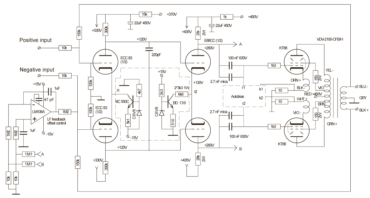
Global feedback
An alternative circuit has been investigated with a more "classical" large global feedback. The main difference is that the local feedback over the gain and driver stages is omitted and a main pole is added by a 220pF capacitor between the anodes of the ECC83. The resulting loop-gain is now 26+8=34 dB and the open-loop bandwidth is approximately 5 kHz. There are several objectively observable favorable effects like the very low output impedance of <0.1 Ohm (damping factor of >80) and a lower distortion level (see measurements section). Still it is often reported in literature that the loop-gain should be frequency independent over the audio band and it might be that the perceived difference in sound quality is due to the 5 kHz open-loop bandwidth. Anyway, the circuit with local instead of global feedback is more appreciated in listening tests.
It should be noted, that the necessity to keep the gain over the audio band independent of the frequency, implicitly excludes Op-Amps from audio applications. Before jumping into conclusions one should be aware that most audio signals, delivered by modern audio equipment (including Vinyl!), have passed a large amount of Op-Amps before arriving at the power amplifier. This all underlines that perceived performance in the audio field can often not be be easily explained. It might very well be that the system just sounds better because so many people tell that it should sound better. The mind is a famed cheater!
Input circuit
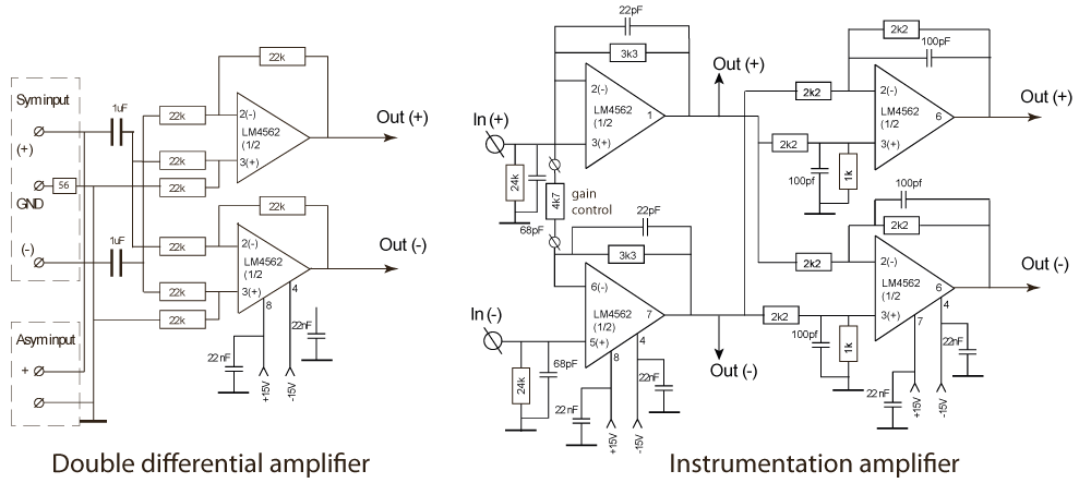
The input of the tube amp requires a fully symmetrical signal from a low impedance pre-amplifier. For those of you who want to apply a non-symmetrical or single ended pre-amplifier or prefer a high impedance input you can add one of the following input signal amplifiers if you have no objections against Op-Amps. When the signal is not fully symmetric, you can use the double differential amplifier like the one shown below at the left side. When a high input impedance is required, the instrumentation amplifier at the right side is better in also having a lower common-mode rejection ratio. When the input signal is symmetric the outputs of the first Op-Amp pair can be used as inputs for the tube amplifier. If the symmetry is not sufficient a double differential amplifier can be added. In this case with lower resistor values which is better for the noise level.
Finally one can add input coupling capacitors like shown with the double differential amplifier in case one does not trust the DC level of the pre-amp output.